R&D Support - Design, Detailing, Manufacturing, Prototyping & Testing
Manufacturers, universities & research laboratories out-source engineering design, development & test activities to Validata.
Aerospace & automotive component testing
Copyright Validata 2010 All rights reserved
UK VAT number GB 8362918 08
Oil E&P Proof of Concept Project - Down Hole Liner Expansion Tool
PROJECT OBJECTIVE : To develop a low power wire line tool for down hole expansion of
tubular liners. In service the liners would be expanded radially outwards against the bore of
perforated well casings in order to prevent the passage of production fluids
and crude oil that would ordinarily flow though the casing’s perforations.
Responsibility for this Proof of Concept project
was entrusted to Validata. The work package encompassed all design, manufacturing and
testing activities in a 3 phase programme. The client’s specification data was very brief and consisted of only the well
casing and liner diameters and a conceptual sketch of one
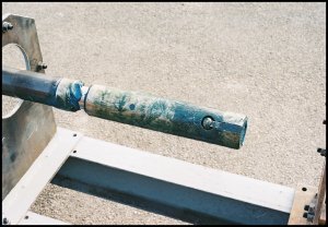
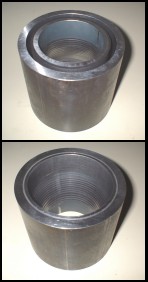
potential tool mechanism. The samples, shown below, demonstrate the project's
successful outcome. The two ends of a 6” length of casing show both the
original and the fully expanded ring seal and illustrate the short tapering
transition that the system can produce.
Phase 1 was an evaluation of existing pipe expansion technologies and a simple approach,
based on the use of steel rollers, was rapidly identified. The selected process is widely
used to seal the ends of heat exchanger tubes and examples of these tools are
cheap and readily available. Validata designed a small hand powered rig to
evaluate one of these tools through a series of simple but controlled liner
expansions. The rig was strain gauged, which enabled the logging of torque data
by a NI / LabView data acquisition system. The tests verified the technology's
practicality and provided data that was useful for estimating the power requirements
needed to drive an automated expander. Unfortunately the tool had fundamental
limitations; It didn't have the necessary operating range. It could only expand
a 75 mm length of tube and it only had a 2% radial expansion ratio, these were far short
of the targets of 20% radial expansion over a 10m length.
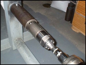
Phase 2 was the 1st redesign of the expansion tool. The new design included the replacement of conventional cylindrical expansion rollers with
ball bearings. This increased the maximum expansion ratio by an order of magnitude. Elimination of
the roller bearings also removed the self feeding feature of the tool and
necessitated the addition of a separate drive to push the tool along the liner.
The second phase of tests demonstrated the success of the new design but also
revealed that any radial expansion was accompanied by a similar axial elongation.
This was a very significant observation because it implied that in a real application of this technology the liner's length would increase upon expansion into position.
Once again, data logging allowed measurement of forces, torques and,
most importantly, torque and power start-up surges, data which is critical
for the design of production tools.
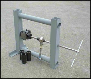
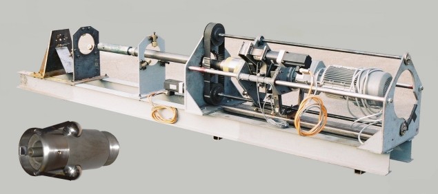
In Phase 3, the final stage, an electrically powered prototype was designed and tested. Once again the test pieces were restrained
by purpose made load cells which monitored critical torques and thrusts. An
a.c. servo control system allowed precise control of the expanded diameter at
any axial position. Programmable control of the 3 axis machine enabled either
fully automatic or manual production of complex expansion profiles. These
included long continuous long patches or multiple short ones. The multiple
short patches minimised the increase in liner length and also created sealed
annular cavities between the casing and the unexpanded portions of the liner.
The cavities were hydraulically pressurised to demonstrate a) the sealing capability
at the expansion points and b) the liner's collapse pressure and how it was
effected by the geometry of the expansion regions.
The final expander lance, which passes along the liner's bore, can be seen to the right.